
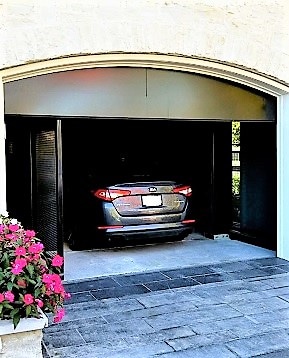
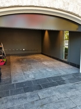
This project started out as a simple installation of a traditional automobile “scissor” lift for a customer’s garage. Like many lifts, this unit was designed to comprise two levels allowing a car to be lowered into the basement, on the lower deck for storage, while leaving a steel deck over the hoistway in the garage’s main floor to allow parking of a second vehicle above the lowered car. The customer for this project had some very particular demands for the aesthetics, including imposed limitations for the elevator guide system that presented some unique challenges.
We wanted to be able to lower a vehicle into the basement, rather than simply leaving it on the elevator for “storage,” as is typical for this type of lift. For this design, an exit door was to be provided in the basement to allow the user to drive off the lift and park in the underground area. In addition, no guide rails were to be installed extending above the floor of the garage. This led us to apply the scissor lift-style elevator. To add one more proverbial fly to the ointment, the user was to be able to operate the car elevator from inside the vehicle so they could enter, exit and park their car seamlessly.
The real challenges began when the contractor started to dig the foundation for the home and hit ground water where the elevator pit was to be located. The 26 in. required for the scissor lift drive equipment was no longer going to be possible. In fact, the maximum pit depth that would be available was estimated at roughly 8 in. This is where the real design complications started to pile up: We had to come up with a solution that would still meet the general requirements for capacity, travel and power consumption, but would also be able to fit in a shallow, 8-in. pit. Further, it would be required to have no guide rails extending above the upper garage floor level.
We developed some concepts for accomplishing this using traditional elevator design approaches, but none were able to satisfactorily conform to all of the limitations we faced. We knew we would have to get creative and ignore our usual tendencies toward traditional elevator design approaches if we were going to pull this off.
This is where our “four-post” hydraulic drive system for the unit became a promising choice. It allowed us to maintain support under the varying load conditions during loading and unloading, as well as the security of four “locked columns of oil” to offer additional stability to the unreasonably short guide mechanism we would need to employ if we were going to fit into the shallow pit. We would also need a synchronization system of some kind to keep the four hydraulic jacks in sync with one another.
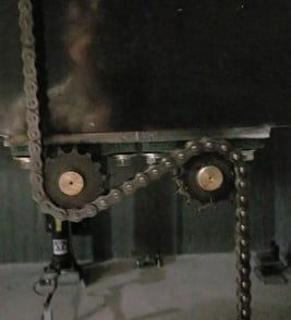
Due to the travel, pit and overhead relationships, we were forced to select two-stage synchronous hydraulic jacks for the main lifting system. This meant that our synchronization mechanism would have to be more positive than simply “fixing” the jacks together to a solidly supported structure. While this approach is well proven in the industry, its implementation would require a significant vertical distance between the guide shoes, in order to ensure a “rigid” connection between the jacks. Since the guide rails would have to stop just below the upper floor level, and the pit was going to be only about 8 in. deep, we simply would not be able to make this work. For this reason, we took a look at mechanical synchronization systems used in other industries to see if there was something that could be adapted to work in our configuration. We chose a roller chain and sprocket design approach, as it was compact enough to fit in the close running clearance between the upper floor cutout and the elevator car and was versatile enough to allow us to contain the entire interconnection system that would link the four jacks together in the limited space below the main platform.
We ran four vertical chains dead-ended at the top and bottom and woven around two sprockets to capture the movement of the platform and translate it to rotation (Figure 1). We then used interconnecting shafts to synchronize the rotation to the other vertical chains on the opposite side of the lift (Figure 2). The inner two shafts were then linked together with another chain to tie all four vertical chains together (lower right of Figure 2).

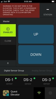
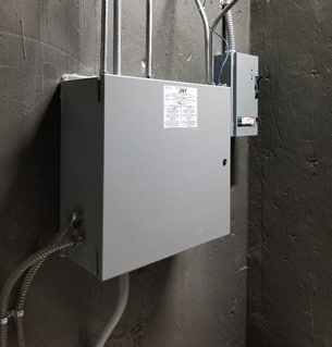
We chose a constant pressure control system to ensure “line-of-sight” operation of the lift at all times for safety. The only exception to this would be when operating the lift from the basement control station. In this case, the user would essentially be running blind to the upper floor level. For this reason, we limited the control station at the basement landing to call only, thereby preventing the ability to run it up from the basement landing control station. To allow operation of the lift from inside the vehicle, we decided to employ remote control technology and provided wired car operating panels and traveling cables to allow operation from the platform, should it fail. We took on the development of a smartphone app suitable for both iOS and Android devices, and a Wi-Fi interface to the elevator controller to accomplish this goal. Our development of the application touched on a great number of interesting approaches to integrating safety and security into the system.
We created an interface that would permit integration into the user’s smart-home system or allow a standalone Wi-Fi connection completely separate for the smart-home. This would give the user a choice of implementations, as well as provide the security inherent with modern Wi-Fi systems. At one point, we even toyed with the addition of a camera interface to allow an image of the lift to be displayed on the app. This would allow the user to verify that the lift was clear and safe to operate. We developed the system, but chose not to integrate this in favor of a more positive obstruction-detection system.
The application was implemented and tested on both iOS and android platforms and was installed on this unit for use (see Figure 3).
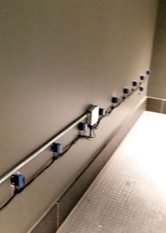
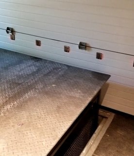
All this, of course, meant there was now the potential for the lift to be operated from almost anywhere with a connection to the Wi-Fi router and be run blind to the upper garage level. For this reason, we chose to implement a more positive obstruction detection system that would prevent the lift from running at all if the upper deck were obstructed in any way. We added a series of light-ray sensors to the garage area over the upper deck to ensure the lift would not operate unless the upper deck and immediate surrounding area were clear of obstructions. We tied this into the main elevator controller and interrupted the safety circuit when an obstruction was detected. With all of these features integrated into the lift, we now felt the level of safety and adherence to the intents of the elevator code were satisfied.
To date, the lift has been operating while the homeowner has been working on finishing touches to enclose the light beam array and apply an epoxy finish to the platform and upper deck. We will also be upgrading the car and landing control stations to replace the industrial looking buttons and indicator lights with something a little more elegant.
The end result is:
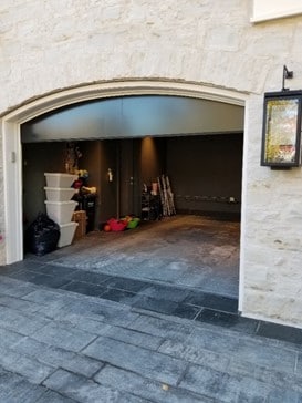
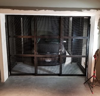
- A car elevator that allows normal parking in the main garage and becomes essentially “invisible” when not in use.
- A smartphone-enabled constant pressure remote control system that verifies line of sight by the user allowing operation.
- An 8,000-lb capacity car elevator that runs on 220V 1 phase residential power and requires only an 8-in.-deep pit.
- A Wi-Fi enabled interface to an elevator controller that seamlessly integrates into current “smart home” technology.
- A fully synchronized set of four 2-stage synchronous telescopic hydraulic jacks using an innovative implementation of mechanical interconnection.
Project Details
Location: Mississauga, Ontario Canada
Building type: Private Residence
Applied codes: CSA B44/ASME A17.1-2010, CSA C22.1, OBC (Ontario Building Code) Classification: Material Lift Type B (with variances)
Rated load: 8000 lb (3640 kg)
Loading: Class ‘B’ (Automobile)
Drive: Quad synchronous telescopic direct hydraulic
Guide rail: Custom Dual V guide rail with machined V-groove rollers
Platform size: 10 ft, 6 in. (3,200 mm) x 20 ft, 0 in, (6,096 mm)
Upper deck size: 11 ft, 0 in. (3,353 mm) x 20 ft, 6 in. (6,248 mm)
Travel: 11 ft, 4-5/8 in. (3471 mm)
Pit depth: 1 ft, 0 in. (305 mm) with 8 in. (204 mm) usable
O/H clearance: 10 ft, 10 ½ in. (3315 mm)
Rated speed: 8 ft/min (0.04 m/s), nominal
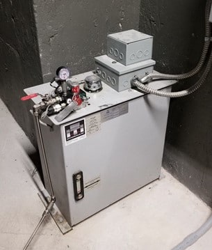
Power unit: 220V 1 phase, 60 Hz, 10 hp submersible pump motor with helical screw pump
Control valve: Blain KV1P — 120V coil
Controller: JRT Model JML-1000
Landing doors: Upper garage door and lower 3-section horizontal sliding door with mechanical lock and contacts on both. Power operated.
Credits
Designer/Developer: Queenscorp Group, Ontario, Canada
Elevator contractor: Quest Elevator Co., Ltd., Ontario, Canada
Equipment manufacturers: Quest Elevator Co., Ltd.; Avro Tower Cranes, LLP, Ontario, Canada
Component manufacturers: ITI Hydraulik, Quebec, Canada; Automatisation JRT, Inc., Quebec, Canada